by

PonyProg2000 documentation
by
Last update $Date: 2008/01/05 22:57:06 $
Installing PonyProg depend on the system you have.
With Windows95/98/ME or NT/2000/XP just run the Setup.exe and follow
the instructions.
With RedHat Linux 6.2/7.0 login as root and execute the command
# tar xvfzP ponyprog-X.XXX.tar.gz
# chmod +s /usr/local/bin/ponyprog2000 (optional)
If you want to use parallel port interfaces without run PonyProg as root you
need also a 2.4.x kernel and parport, parport_pc and ppdev
kernel modules. insmod all three modules before to execute PonyProg.
If you want to use serial port interfaces be sure you have the rights to read/write
the /dev/ttySx devices and /var/lock directory. With RedHat you may want to
add your user to uucp group.
The first time you run the program remember to select the interface and port
you use with the Setup. If the program
report a message like "The interface don't respond" when started,
it means that you not have configured the port properly, or the interface is
not connected.
You need also to run Calibration in most
cases.
The following is an explanation of each menu command.
Open a new window, each window display a buffer for the device selected.
Open a file by name, and read its content in the current window. You can select the file to open through a dialog or drag and drop the file to open over the PonyProg window. PonyProg recognize several different types of file format: e2p, intel hex, motorola S-record and raw binary. If the selected file doesn't seem to be a e2p, it tries to open the file as intel hex; if this operation fails, then it tries to open the file as S-Rec; if also this operation fails, then it opens the file as binary. If the file has e2p format, you don't need to worry about the device type currently selected, otherwise you first have to select the correct device type, then load the file. In case of splitted Program/Data device like AVR and PIC the content of the data eeprom will be displayed after the content of the program flash memory in the current window with a different color.
This command is available only for splitted Program/Data devices. The buffer is splitted in two different part for these devices: the first part for program memory and the second part for data memory. This command Open a file by name and load only the program memory. You can select the file to open through a dialog. The file to load may have one of these format: intel-hex, motorola S-record or raw binary.
This command is available only for splitted Program/Data devices. The buffer is splitted in two different part for these devices: the first part for program memory and the second part for data memory. This command Open a file by name and load only the data memory. You can select the file to open through a dialog. The file to load may have one of these format: intel-hex, motorola S-record or raw binary.
Save the content of current window buffer to a file. If no name has been specified it works like Save as.
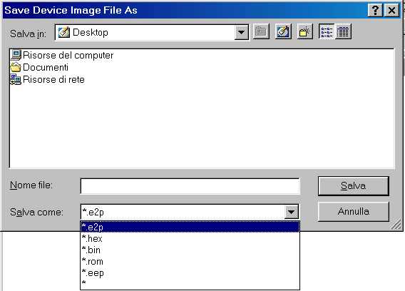
Open a dialog box where you can specify the name of the file. In the bottom of the dialog box you can select the file format for the file to save (indicated by the extension). If you press OK the content of the current window will be saved in the file specified. I suggest to save always in e2p format, doing so the device type and the notes will be recorded in the file. The .bin format is raw binary format, it's commonly used to export the file to other programs.
This command is available only for splitted Program/Data devices. The buffer is splitted in two different part for these devices: the first part for program memory and the second part for data memory. This command save the content of current window buffer program memory to a file. A dialog box asks you the name of the file to save and the file format by selecting the extension.
This command is available only for splitted Program/Data devices. The buffer is splitted in two different part for these devices: the first part for program memory and the second part for data memory. This command save the content of current window buffer data memory to a file. A dialog box asks you the name of the file to save and the file format by selecting the extension.
This command reload last opened files in the current window buffer. It's useful when you need to edit/build the files from an external program (assembler/compiler) and you need to repeat the same cycle: compile - load file - write device more than one time.
Open a dialog box where you can select the printer name and options. If you press OK the content of the current window will be printed.
Close the current window, if there is only one opened window a dialog window asks you if you want to exit; you can choose Yes or No. If the current window buffer is modified a dialog window asks you if you want to save the content in a file before to close the window.
Close all the opened window and exit the program. If there is a modified window buffer a dialog window asks you if you want to save the content to a file before to close the window.
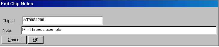
Open a dialog box where you can edit a Chip id and a note. These two fields are saved within the window buffer if you use the e2p file format (see Open). These two fields are free text editing, and are useful for a description of the device programmed and the meaning of its content.
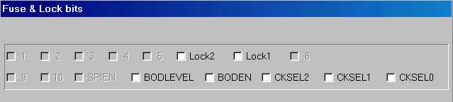
Open a dialog box where you can edit a device specific Configuration and Security bits. This dialog is especially useful for microcontrollers, because they could not work at all without set these bits in a correct way. The following screen dumps show the configuration bits for some microcontroller families. Note that disabled bits (grayed) are not used or not modificable.
AVR AT90S4433 Security and Fuse bits
PIC 16F84
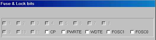
| FOSC1 | FOSC0 | Status |
| not checked | not checked | RC resistor/capacitor oscillator |
| not checked | checked | HS high speed crystal/resonator oscillator |
| checked | not checked | XT crystal/resonator oscillator |
| checked | checked | LP low power oscillator |
AT89S8252
Microchp 24C65
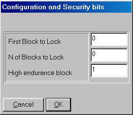
The dialog ask you to insert the first block and the number of blocks to lock. When the device is locked you can't do a "write security" or a "write high endurance" anymore. To lock the device the number of blocks must be greater than 0.
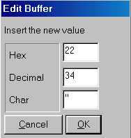
You can toggle this item either to enable or disable the edit mode. If the edit mode is enabled you can modify the buffer content by clicking on a location of the current window. Two editing modes are available: hexadecimal editing and text editing. If you click on the HEX (center) part of the screen or press ENTER you open a dialog where you can insert the new value for that byte in decimal, hexadecimal, or character. If you click on the ASCII (right magenta) part of the screen you open a dialog where you can insert or modify a text starting from that location. You can CUT & PASTE in the text entry dialog by the use of the right mouse button. Note that you can enable/disable only the edit mode of the current window, so if there are more than one buffer window opened, the edit mode of other windows are left unchanged.
Select the type of current device. You have to select the device type before
any commands (read, writing, open, save, ...). Selecting an "Auto XXX"
type means that the device type is determined by the program during the read
or write operation, this feature is useful when you need to query a device to
know if it works and which device it is. There are some different device family:
the I�C Bus eeproms that are addressed with 8 bit word, the I�C Bus eeproms
that are addressed with 16 bit word, the Microwire eeproms with 8 bit organization,
the Microwire eeproms with 16 bit organization, the SPI eeproms, the AVR microcontrollers,
the PIC 16 microcontrollers, the IMBus eeproms and SDE2506 eeprom. You can select
the device family in the tool bar with the combo-box, or directly the device
type in the menu. The current device type is stored in the .INI file, so the
next time you run the program it's recalled. To read and write I�C Bus eeproms
other than 24xx (i.e. the SDE2526, SDA2546, SDA2586, SDA3546, SDA3586) select
the type "24XX Auto".
The 24C01 can be readed but not writed, you can read it as a 2402 or 24XX Auto
device. Note that you can often replace a 24C01 eeprom with a new 24C02 eeprom,
because it's fully compatible to the 24C01.
Several microwire eeproms support two types of word organization: 16 bit organization
and 8 bit organization. The organization is selected with a pin connected to
VCC or GND. SI-Prog adapter connect this pin for 16 bit organization, however
some devices support only 8 bit organization.
Read the content of a device in the current window buffer. This operation
can take a while to execute, so a dialog box shows the operation progression.
If you want to stop the current read just press the "Abort" button.

Finally a dialog box showing the result of the operation appears.
If the program report the message "Device not responding" means that
you missed to connect the device to read, or the interface is not configured
properly (see the Setup). Note that only
the devices that support probing report this type of message, other device simply
read all 0's of FF's (if the device is missed). The devices that support probing
are the 24XX, the AVR and some PIC. In the case of AVR device selected,
the program can report the message "Device locked" in case of the
locked bits was programmed. Even some preproduction devices don't support auto
probing. You can't read a locked device, to program it see Write.
Since version 1.15c if you select an AVR device (AT90S2313
for example) and read it, the program try to probe the device first. If the
device is missing, or the device is locked, or the device is a preproduction
device a dialog box appears. It asks you if you want to abort operation, retry
or ignore the error. In case of a preproduction device just select "Ignore".

This command is available only for splitted Program/Data devices. The buffer is splitted in two different part for these devices: the first part for program memory and the second part for data memory. This command read only the program memory from the device, and leave the data memory intact.
This command is available only for splitted Program/Data devices. The buffer is splitted in two different part for these devices: the first part for program memory and the second part for data memory. This command read only the data memory from the device, and leave the program memory intact.
Read security and configuration bits from the device. Note that this command is implemented only for some devices. To modify the security and configuration bits refer to edit command.
Write the content of the current window buffer to a device. A dialog box ask
you to confirm this unrecoverable operation. This operation can take a while
to execute, so a dialog box shows the operation progression. If you want to
stop the current write just press the "Abort" button. After the write
operation an automatic verify is executed. Finally a dialog box showing the
result of the operation appears.
Before to perform a write I suggest to select the exact device type, not the
"24XX Auto" or "AVR Auto".
Note that both the program (FLASH) and data (EEPROM) memory are writed (only
if the device is a splitted device like the AVR or PIC), and then verified.
Since the version 1.15c a probe is performed on every AVR device (see Read).
This command is available only for splitted Program/Data devices. The buffer is splitted in two different part for these devices: the first part for program memory and the second part for data memory. This command write only the program memory to the device, and leave the data memory intact. The exception is the AVR device: to write the program memory an erase is needed, so the data memory is erased too. Some AVR devices have EESAVE fuse bit, when programmed the EEPROM is preserved during a flash erase.
This command is available only for splitted Program/Data devices. The buffer is splitted in two different part for these devices: the first part for program memory and the second part for data memory. This command write only the data memory to the device, and leave the program memory intact.
Write security and configuration bits to the device. Note that this command is implemented only for some devices. To modify the security and configuration bits refer to edit command.
Verify the content of a device, compares it to the content of the current window buffer. This operation can take a while to execute, so a dialog box shows the operation progression. If you want to stop the verify just press the "Abort" button. Finally a dialog box showing the result of the operation appears.
This command is available only for splitted Program/Data devices. The buffer is splitted in two different part for these devices: the first part for program memory and the second part for data memory. This command verify only the program memory from the device, and ignore the data memory.
This command is available only for splitted Program/Data devices. The buffer is splitted in two different part for these devices: the first part for program memory and the second part for data memory. This command verify only the data memory from the device, and ignore the program memory.
Erase all the content of a device to FF's (both program and data memory). Note that this command is implemented only for AVR and PIC devices.
Shows some informations about the device. Some of these informations are showed also in the status bar at the bottom of the main window.
Reset the device. It's useful with in-system applications.
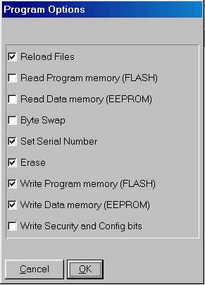
Execute a customizable sequence of commands. You can select the commands to execute with program options
Select the commands to execute with the Program command.
Clear the current window buffer with FF's.
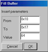
Fill the current window buffer with a character. A dialog box asks you to select
the addresses fo fill (from - to locations), and the value of the character
to fill. You can insert the value either in decimal (i.e. 45), hexadecimal (i.e.
0x45) or octal (i.e. 045) base.
This command duplicates every bank in the current buffer and changes the device type to a bigger device type. A bank is a cluster of 256 bytes for the 24xx and a word for other devices. This utility is useful to replace a SDA2546 device with a 24C08 or a SDA2586 with a 24C16. Example: you have to select the device type "24xx Auto", connect the SDA2546 device and perform a Read operation. Then you have to perform a "Double bank", replace the SDA2546 with a blank 24C08 and perform a Write operation (Refer also to I2CBus adapter).
This command swap bytes within every word in the current window buffer. It's
useful to convert from little endian representation to big endiand and viceversa.
Some devices uses 16bit word so you can represent it in both ways depending
on your needs.
For example consider the number 1234 hex (4660 decimal), the little endian is 34 - 12,
while the big endiand is 12 - 34.
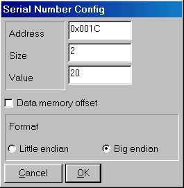
This command set the serial number in the configured locations of the current window buffer. You can configure the serial number location, value and size with the serial number config command. Every time you execute this command the value is incremented.
This command open a dialog box where you can configure the serial number locations,
value, format and size.
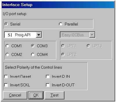
Open a dialog box where you can select the interface type and the port number where the hardware is connected. You can choose from several hardware interfaces (see PonyProg Hardware interfaces for more info). Note that only SI Prog support all devices.
Calibration tunes the serial bus speed for your computer. When you run Calibration
be sure that PonyProg is the only program running in the PC, and the hard disk
is idle (look at the HD led). If your PC is busy because it's performing other
tasks the Calibration thinks your PC is slower than actual speed, and all I/Os
are performed without proper delay.
After the Calibration you can choose the speed for every serial bus modifying the
following parameters in the ponyprog.ini (.PonyProgrc under Linux) file:
Every parameter can be assigned the value ULTRASLOW, VERYSLOW, SLOW,
NORMAL, FAST or TURBO.
Avoid to use the TURBO value because it means "no delay", and
probably it doesn't work on your PC, especially with the I/O driver.
Just for example my PC (Pentium MMX 200MHz) run I�CBus at about 80Khz with NORMAL,
and 110 Khz with FAST. Note that a lot of I�CBus devices don't work
at speed above the 100KHz.
A special note for AVR devices. The AVR need a valid system clock to be programmed via SPI and the max frequency of the SPI bus depends on this system clock. So if you changed the fuse (even accidentally) to use low clocks like 1MHz or 32.768KHz you must change the SPIBusSpeed=VERYSLOW or ULTRASLOW to access the AVR anymore. If you have to use such low clocks I suggest to program the flash and eeprom first, and at last program the security and fuse bits.
PonyProg supports several hardware interfaces, however note that only with
SI-Prog interface you are able to program all the devices.
Next paragraphs show to you all the hardware interfaces in detail.
Connect the DB9 connector to PC COM port using standard serial
cable.
Connect J2 connector to the correct adapter observing polarity (look at pin
1 and pin 10).
This adapter is needed to program all I�CBus devices: 24C02, 24C04, 24C08,
24C16, 24C32, 24C64, 24C128, 24C256, 24C512, PCF858x and SDA2526, SDA2546, SDA2586
eeproms. Connect the adapter to main board observing polarity. Insert the eeprom
in the socket with the signature: 24xx (A0). If you need to access a 24xx eeprom
with SMT case (SO8) place the device with every pin exactly on the corrisponding
pad and press to make the contact good during the read/write operation.
Some devices mount two 24Cxx eeproms at different address and access them as
a large single eeprom. You can achieve this with the two sockets A0 and A2.
For example if you insert two 24C02 eeproms, select the "24XX Auto"
device and perform a read. PonyProg detect a 24C04 eeprom and the content is
the sum of the two 24C02 eeproms.
Some eeproms (especially old SDE and SDA eeproms) need external power for a
correct programming.
To use external power you need to connect a 9V battery to J9 and move JP2 to
"ext" position.
This adapter is needed to program the Microwire devices: 93C06, 93C46, 93C56, 93C66, 93C76, 93C86 eeproms. Connect the adapter to main board observing polarity. Insert the eeprom in the socket with the signature: 93Cx6 or 93Cx6X depending on the exact device model. Note that some devices support only 8 bit organization, look at the following table to know what socket to use and menu device to select.
Microchip Microwire (3-wire) Serial eeprom
|
Part Code |
Org. |
Socket |
Power (*) |
Menu Label |
|---|---|---|---|---|
|
93AA46 |
8/16bit |
93Cx6 |
Ext/Int |
MicroWire 16 -> 9346 |
|
93LC46A |
8bit |
93Cx6 |
Ext/Int |
MicroWire 8 -> 9346 |
|
93LC46B |
16bit |
93Cx6 |
Ext/Int |
MicroWire 16 -> 9346 |
|
93C46B |
16bit |
93Cx6 |
Ext |
MicroWire 16 -> 9346 |
|
93AA46X |
8/16bit |
93Cx6X |
Ext/Int |
MicroWire 16 -> 9346 |
|
93LC46AX |
8bit |
93Cx6X |
Ext/Int |
MicroWire 8 -> 9346 |
|
93LC46BX |
16bit |
93Cx6X |
Ext/Int |
MicroWire 16 -> 9346 |
|
93C46BX |
16bit |
93Cx6X |
Ext |
MicroWire 16 -> 9346 |
|
93AA56 |
8/16bit |
93Cx6 |
Ext/Int |
MicroWire 16 -> 9356 |
|
93LC56A |
8bit |
93Cx6 |
Ext/Int |
MicroWire 8 -> 9356 |
|
93LC56B |
16bit |
93Cx6 |
Ext/Int |
MicroWire 16 -> 9356 |
|
93C56A |
8bit |
93Cx6 |
Ext |
MicroWire16 -> 9356 |
|
93C56B |
16bit |
93Cx6 |
Ext |
MicroWire 16 -> 9356 |
|
93AA56X |
8/16bit |
93Cx6X |
Ext/Int |
MicroWire 16 -> 9356 |
|
93LC56AX |
8bit |
93Cx6X |
Ext/Int |
MicroWire 8 -> 9356 |
|
93LC56BX |
16bit |
93Cx6X |
Ext/Int |
MicroWire 16 -> 9356 |
|
93C56AX |
8bit |
93Cx6X |
Ext |
MicroWire16 -> 9356 |
|
93C56BX |
16bit |
93Cx6X |
Ext |
MicroWire 16 -> 9356 |
|
93AA66 |
8/16bit |
93Cx6 |
Ext/Int |
MicroWire 16 -> 9366 |
|
93LC66A |
8bit |
93Cx6 |
Ext/Int |
MicroWire 8 -> 9366 |
|
93LC66B |
16bit |
93Cx6 |
Ext/Int |
MicroWire 16 -> 9366 |
|
93C66A |
8bit |
93Cx6 |
Ext |
MicroWire16 -> 9366 |
|
93C66B |
16bit |
93Cx6 |
Ext |
MicroWire 16 -> 9366 |
|
93AA66X |
8/16bit |
93Cx6X |
Ext/Int |
MicroWire 16 -> 9366 |
|
93LC66AX |
8bit |
93Cx6X |
Ext/Int |
MicroWire 8 -> 9366 |
|
93LC66BX |
16bit |
93Cx6X |
Ext/Int |
MicroWire 16 -> 9366 |
|
93C66AX |
8bit |
93Cx6X |
Ext |
MicroWire16 -> 9366 |
|
93C66BX |
16bit |
93Cx6X |
Ext |
MicroWire 16 -> 9366 |
|
93AA76 |
8/16bit |
93Cx6 |
Ext/Int |
MicroWire 16 -> 9376 |
|
93LC76 |
8/16bit |
93Cx6 |
Ext/Int |
MicroWire 16 -> 9376 |
|
93C76 |
8/16bit |
93Cx6 |
Ext |
MicroWire 16 -> 9376 |
|
93AA86 |
8/16bit |
93Cx6 |
Ext/Int |
MicroWire 16 -> 9386 |
|
93LC86 |
8/16bit |
93Cx6 |
Ext/Int |
MicroWire 16 -> 9386 |
|
93C86 |
8/16bit |
93Cx6 |
Ext |
MicroWire 16 -> 9386 |
(*) If you experiment problems during the “write” operation, use the “Ext” power. “Int” power may not work on some PC, it depends on how much current is capable your PC COM port. If you don't use the LM2936Z-5 use the “Ext” power with ALL devices.
Atmel Microwire (3-wire) Serial eeprom
|
Part Code |
Org. |
Socket |
Power (*) |
Menu Label |
|---|---|---|---|---|
|
AT93C46 |
8/16bit |
93Cx6 |
Ext/Int |
MicroWire 16 -> 9346 |
|
AT93C46W |
8/16bit |
93Cx6 |
Ext/Int |
MicroWire 16 -> 9346 |
|
AT93C46R |
8/16bit |
93Cx6X |
Ext/Int |
MicroWire 16 -> 9346 |
|
AT93C46A |
16bit |
93Cx6 |
Ext/Int |
MicroWire 16 -> 9346 |
|
AT93C46C |
16bit |
93Cx6 |
Ext/Int |
MicroWire 16 -> 9346 |
|
AT93C56 |
8/16bit |
93Cx6 |
Ext/Int |
MicroWire 16 -> 9356 |
|
AT93C56W |
8/16bit |
93Cx6 |
Ext/Int |
MicroWire 16 -> 9356 |
|
AT93C66 |
8/16bit |
93Cx6 |
Ext/Int |
MicroWire 16 -> 9366 |
|
AT93C66W |
8/16bit |
93Cx6 |
Ext/Int |
MicroWire 16 -> 9366 |
|
AT93C86 |
8/16bit |
93Cx6 |
Ext/Int |
MicroWire 16 -> 9386 |
(*) If you experiment problems during the “write” operation, use the “Ext” power. “Int” power may not work on some PC, it depends on how much current is capable your PC COM port. If you don't use the LM2936Z-5 use the “Ext” power with ALL devices.
To use external power you need to connect a 9V battery
to J9 and move JP2 to "ext" position.
This adapter is needed to program the Microchip PIC microcontrollers: PIC16F84,
PIC16F84A, PIC16F87x, PIC12C50x. Connect the adapter to main board observing
polarity. Insert the PIC in the correct socket (look at the text in silkscreen
on the PCB). Pay attention to polarity (pin 1).
To program PIC16F84, PIC16F84A and PIC16F87x you need a 9V battery connected
to BT1, the JP2 on "Int" position, and the JP1 on "Bat"
position. If your COM port can't provide enaugh current you have to provide
an external power: connect a stabilized +15 Volt D.C. to J9 (pay attention to
the polarity), move JP2 on "Ext" position and JP1 on "Ext"
position.
To program PIC12C50x you need a stabilized +13 Volt D.C. to J9 and move JP2
on "Ext" position and JP1 on "Ext" position.
Version 2.2 of PDF schematic
| Jumper name (silkscreened on the PCB) | Jumper function |
| JP1 | Switch between battery powered and external powered PIC Vpp modes. |
| JP2 | Switch between internal COM powered and external powered Vdd modes. |
| JP3 | Select the polarity of Reset line for AVR AT90Sxx and AT89Sxx microcontroller |
| JP4 | Connect pin 7 to GND. 24Cxx devices usually need this pin connected to GND, while PCF8582 no. |
| J9 |
Connector for Vdd external power. You need to provide an external power (9V, i.e.battery) when the Vdd drops under 5 Volts during programming. This may happen in three cases:
|
| BT1 | Connector for Vpp battery generated power. PIC16Fxxx devices need a battery to generate the Vpp = Vdd + 9V |
To use PonyProg you need a serial cable DB9 Female to DB9 Male with ALL pins connected in the following way:
| DB9 Female | DB9 Male |
| 1 | 1 |
| 2 | 2 |
| 3 | 3 |
| 4 | 4 |
| 5 | 5 |
| 6 | 6 |
| 7 | 7 |
| 8 | 8 |
| 9 | 9 |
It's sometime called "modem cable", however check that all pins are connected. Avoid to use "null modem cable"s.
Version 2.2 of PDF mounting plan
PonyProg SCRIPT is a tool to automate programming. A script is a text file with extension .e2s containing a sequence of commands to execute. Every line contain a command, lines starting with the character # are skipped (comments) as well as blank lines.
With your favourite text editor create a text file like this:
#------ START --------
#Programming sequence
SELECTDEVICE ATTINY12
CLEARBUFFER
LOAD-PROG flash.hex
LOAD-DATA eeprom.hex
PAUSE "Connect and powerup the circuit, are you ready?"
READ-CALIBRATION 0x3ff
ERASE-ALL
WRITE&VERIFY-ALL
#Pay attention to NOT disable RSTDISBL
#Fuse: "BODLEVEL ","BODEN ","SPIEN ","RSTDISBL ","CKSEL3 ","CKSEL2 ","CKSEL1","CKSEL0 "
# 1 1 1 0 1 1 0 1
WRITE-FUSE 0xED
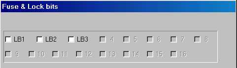
#Lock: {X,X,X,X,X,"Lock2 ","Lock1 ",X}
# 0 0 0 0 0 1 1 0
WRITE-LOCK 0x06
#------- END ---------
Save the file with extension .e2s (for example script.e2s) and then run:
> ponyprog2000.exe script.e2s
PonyProg will startup, select the ATtiny12 device, clear the buffer, load flash
and eeprom files, read the osc.calibration to location 0x3ff in the buffer and
then program the device with flash, eeprom, fuses and lock bits. When finished
PonyProg exit.
If you use the avr-gcc compiler you will find useful to call PonyProg directly
from the make file.
Insert the following lines in your makefile and then launch "make isp"
	ISPEXE = c:/programmi/ponyprog2000/ponyprog2000.exe
	MCU = atmega128
	TRG = myapp
isp: $(TRG).hex $(TRG).eep
	echo -e "SELECTDEVICE $(MCU)\nLOAD-PROG $(TRG).hex\nLOAD-DATA $(TRG).eep\nWRITE&VERIFY-ALL" >isp.e2s
	$(ISPEXE) isp.e2s
#
BYTESWAP
CALL <command>
CLEARBUFFER
DELAY <msec>
EDIT-SECURITY
ERASE-ALL
FILLBUFFER [val][from][to]
LOAD-ALL [file][relocation_offset]
LOAD-PROG [file][relocation_offset]
LOAD-DATA [file][relocation_offset]
PAUSE [message]
READ-ALL
READ-CALIBRATION <address>[mem][osc_index]
READ-DATA
READ-PROG
READ-FUSE
READ-LOCK
RESET
SAVE-ALL [file | '--'][file_type]
SAVE-DATA [file | '--'][file_type]
SAVE-PROG [file | '--'][file_type]
SELECTDEVICE <device>
SERIALNUMBER [value][start][size][mem][format][autoinc]
VERIFY-ALL
VERIFY-DATA
VERIFY-PROG
WRITE-ALL
WRITE-DATA
WRITE-PROG
WRITE-FUSE [bits]
WRITE-LOCK [bits]
WRITE&VERIFY-ALL
WRITE&VERIFY-DATA
WRITE&VERIFY-PROG
[ ] optional argument
< > required argument
Description:
Any line starting with # character is considered as a comment and skipped.
Description:
Select the device model to read/write.Example:
SELECTDEVICE ATMEGA128
LOAD-ALL
[file][relocation_offset]
LOAD-DATA [file][relocation_offset]
LOAD-PROG [file][relocation_offset]
Description:
LOAD-ALL load the whole content of the selected device from the file specified, this command is useful to load PIC and EEPROM devices with HEX or BIN format, or is useful to load every devices with E2P files.
LOAD-PROG load only the program FLASH portion of the device (useful with the AVR)
LOAD-DATA load only the data EEPROM portion of the device (useful with the AVR)
If no file is specified then open a file dialog to choose the file to load. The relocation_offset is an optional argument useful if you want to load at memory addresses different from that specified in the file. In case of binary file you specify the address from which start to load the buffer.Example:
LOAD-PROG prog_memory.hex
LOAD-ALL memory.bin 0x100 (skip the first 256 bytes of the buffer)
SAVE-ALL
[file | '--'][file_type]
SAVE-DATA [file | '--'][file_type]
SAVE-PROG [file | '--'][file_type]
Description:
SAVE-ALL save the whole content of the selected device to the file specified.
SAVE-PROG save only the program FLASH portion of the device (useful with the AVR)
SAVE-DATA save only the data EEPROM portion of the device (useful with the AVR)
If no file is specified it saves to the current file name, in case of no current file name it opens the file dialog to choose a file name. If the -- string is specified it opens the file dialog to choose a new file name. If you specify the file_type it saves the buffer in the selected file format, useful to convert a file from one type to another.
file_type can be:
- e2p to select the default E2P file used by PonyProg
- bin to select a raw binary format
- csm to select a custom CSM file format used by some TV repairer
- intel-hex to select standard INTEX-HEX text format
- mot-srec to select standard MOTOROLA SREC text formatExample:
SAVE-DATA data_memory.hex intel-hex
SAVE-ALL -- (save all the device and ask the file name)
Description:
READ-ALL read the whole content of the selected device to the current buffer
READ-PROG read only the program FLASH portion of the device (useful with the AVR or PIC)
READ-DATA read only the data EEPROM portion of the device (useful with the AVR or PIC)Example:
READ-ALL
WRITE&VERIFY-ALL
WRITE&VERIFY-DATA
WRITE&VERIFY-PROG
Description:
WRITE&VERIFY-ALL write and then verify the whole content of the selected device reading from the buffer
WRITE&VERIFY-PROG write and then verify only the program FLASH portion of the device (useful with the AVR or PIC)
WRITE&VERIFY-DATA write and then verify only the data EEPROM portion of the device (useful with the AVR or PIC)
WRITE&VERIFY commands require PonyProg version 2.05 or more recent. Usually you will use the WRITE&VERIFY, not the WRITE and then the VERIFY command because the former verify only programmed locations instead the latter verify all the buffer (slower).Example:
WRITE&VERIFY-PROG
WRITE-ALL
WRITE-DATA
WRITE-PROG
Description:
WRITE-ALL write the whole content of the selected device reading from the buffer
WRITE-PROG write only the program FLASH portion of the device (useful with the AVR or PIC)
WRITE-DATA write only the data EEPROM portion of the device (useful with the AVR or PIC)Example:
WRITE-ALL
VERIFY-ALL
VERIFY-DATA
VERIFY-PROG
Description:
VERIFY-ALL read and compare the whole content of the selected device against the buffer
VERIFY-PROG verify only the program FLASH portion of the device (useful with the AVR or PIC)
VERIFY-DATA verify only the data EEPROM portion of the device (useful with the AVR or PIC)Example:
VERIFY-ALL
Description:
ERASE-ALL erase the whole content of the selected device. Usually this operation bring all the locations of the selected device to FF.Example:
ERASE-ALL
Description:
Open the fuse and lock bits dialog to edit them.
Description:
READ-FUSE read the fuse bits (device dependant) and open the fuse and lock bits dialog
READ-LOCK read the lock bits (device dependant) and open the fuse and lock bits dialogExample:
READ-FUSE
WRITE-FUSE [bits]
WRITE-LOCK [bits]
Description:
WRITE-FUSE write the fuse bits (device dependant).
WRITE-LOCK write the lock bits (device dependant).
If the argument is specified it is the numeric value of the bits rapresentation, note that a 1 means programmed. If no argument is specified the current value is programmed. Pay Attention to program the FUSE bits with the AVR, you can specify a wrong bit combination that will prevent you to access the AVR device in the future. Refer to the datasheets for the meaning of every bit.Some AVR devices have more than one byte for the fuse bits. In such cases the argument is a multibyte numer and least significant byte is the standard fuse byte. For example:
argument = 0x010203
Standard fuse = 0x03
High fuse = 0x02
Extended fuse = 0x01
Example:
SELECTDEVICE AT90S1200
#Lock: {X,X,X,X,X,"Lock2 ","Lock1 ",X}
# 0 0 0 0 0 1 1 0
WRITE-LOCK 0x06SELECTDEVICE ATTINY2313
#Fuse: "SPMEN " -
# "DWEN ","EESAVE ","SPIEN ","WDTON ","BODLEVEL2 ","BODLEVEL1 ","BODLEVEL0 ","RSTDISBL " -
# "CKDIV8 ","CKOUT ","SUT1 ","SUT0 ","CKSEL3 ","CKSEL2 ","CKSEL1 ","CKSEL0 "
# 0 - 0 0 0 0 0 1 0 0 - 0 0 0 0 0 0 1 0
WRITE-FUSE 0x00402
SERIALNUMBER [value][start][size][mem][format][autoinc]
Description:
Used to set a serial number in a location in the buffer before to write the device. This number can be specified every time or autoincremented from the previous one.Example:
SERIALNUMBER 136 0x100 2 DATA LITTLEENDIAN NO
Set the serial number of '2' bytes and value '136' at address '0x100' starting from 'DATA' memory. The format should be LITTLEENDIAN without autoincrement
READ-CALIBRATION <address>[mem][osc_index]
Description:
Read the internal oscillator calibration value from the AVR and write it to a location in the buffer at the specified address (and memory type DATA or PROG). The osc_index argument specify which calibration value should be read since some AVR have several oscillator frequencies. The osc_index argument is available only from the 2.06c versionExample:
SELECTDEVICE ATMEGA128
READ-CALIBRATION 0x100 DATA 3
Read the oscillator calibration value for 8MHz frequency
Description:
Swap the order of bytes within a word in the buffer (low byte <--> high byte)
Description:
Reset the device
Description:
Clear the buffer (all bytes to FF)
Description:
Fill the buffer from location 'from' to location 'to' with the 'val' value.
If no argument is specified a dialog ask for these values.Example:
FILLBUFFER 24 0x100 0x200
Description:
Pause the program and show a message dialog asking confirmation to continue.
Description:
Call an external program and wait for it terminates.Example:
CALL notepad.exe
Description:
Wait for the specified amount fo milliseconds.Example:
DELAY 1000
Suspend the script and wait for 1 second
=============
AVR questions
=============

Q: I can't program ATmega, I always got "Write failed message".
Q: I can't program AVR AT90Sxxx, I receive error -21 and the program fails. What is the problem?

A: Increase the following parameters in the ponyprog.ini file (all times are in milliseconds)

   AVRByteWriteDelay=30         'Delay to complete the write of a single word
   AVREraseDelay=100            'Delay to complete the erase of all the memory

   In case of ATmega increase also the following parameter:
   ATMegaPageWriteDelay=50      'Delay to complete the write of a page of flash memory

--------

Q: I can't read or write AT90S1200 device. I receive the error message:
   "Device missing or unknown device -24"

A: Select "Ignore" button, if the final message is "Write succesful" you have a sample that
   doesn't reply to the identify command. It seems that early devices don't reply to this command.

--------

Q: I need to program the AVR mounted on the target circuit (In system programming), but PonyProg
   fails to program because an external reset circuit hold the reset line low for a long time.

A: Try to play with the following parameters in the INI file, it should solve the problem (all the
times are in milliseconds)

  SPIResetPulse=100        'How long is the reset pulse generated by PonyProg
  SPIDelayAfterReset=50    'How many milliseconds PonyProg waits after the reset pulse


===============
Other questions
===============

Q: What type of cable I should use to connect SI-Prog to the COM port?

A: You must use "straight through" cable with all 9 pins connected.
   Don't use "null modem" cable. (look at 3.1.10)

--------

Q: With Windows2000/XP I can't access the LPT ports without being administrator, I need to run PonyProg
   logged in as normal user, what can I do?

A: You cannot load the DLPORTIO.SYS driver w/o being an administrator.
   As Administrator, Start the Computer Management console -> Device Manager -> View: show hidden devices.
   Then Expand Non-Plug and Play Drivers and find the driver in the list.
   It may show up as DriverLINX Port I/O Driver.
   Then, for this driver -> properties -> driver startup. Set startup to boot. Reboot the system.

---------

Q: My PC doesn't have any LPT/COM port, can I use a USB2COM or USB2LPT adapter?

A: Some USB adapters don't work at all while other adapters are very slow. So I suggest to avoid USB adapter
   and buy COM/LPT PCMCIA or PCI adapters that emulates 100% native LPT and COM ports.

----------

Q: I have a Windows2000/XP PC with an extra LPT card, but PonyProg can't select the added port, can I force it?

A: First you have to select the AvrISP-I/O interface instead of the API version.
   Then you have to edit ponyprog2000.ini file and disable port autodetection:
   AutoDetectPorts=NO
   then you have to discover the real address of the extra LPT port by looking at
   Computer Management console -> Device Manager -> LPT ports -> resources. For example if the extra LPT is LPT3
   and the address is DF00 you need to enter the line
   LPTPorts=378,278,DF00
   Note that this fix works only in some version (use 2.06g and newer).